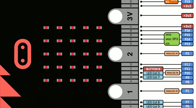
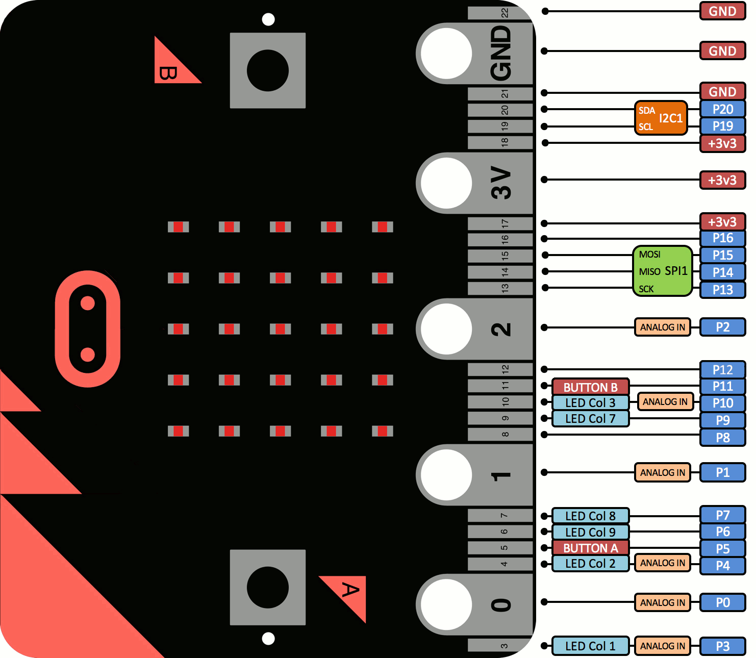
The Micro Bit has a 25 pin edge connector. There are five large “pins” labelled 0, 1, 2, 3V and GND with 20 other pins in-between.
This diagram shows the official pin numbers as well as programmable features available on each pin.
Features
- 6-7 General purpose input output (GPIO) based on configuration.
- 6 Analogue in
- 2/3 reconfigurable PWM outputs
- I2C
- SPI


But where can I find edge connectors to fit it? 80-way 0.05″ un-keyed edge connectors are like hen’s teeth. Why on earth didn’t they use something readily available off the shelf…
Looks like Maplin are starting to sell breakout boards for it. The edge connector choice seems a bit strange but I think the main requirement was that it was easy for kids to hook up wires. The small/large pin arrangement does make this easier but with the side effect that it is a bit quirky from a component point of view.
The joys of market forces. Those connectors are suddenly easy to find.
Kitronik sell an “Inventor’s Kit” for the micro_bit that includes a patch panel and lets you mount the micro:bit on its (included) socket. All you have to add is the micro:bit itself. Probably worth it if you want to get started with hardware hacking, though none of the documentation includes Python.
Can you please udpate the pinout diagram in this article? That seems to be an older revision of the board and it might be a bit confusing 🙂
The latest one is on https://developer.mbed.org/platforms/Microbit/
Thanks for the prompt. It’s updated now.